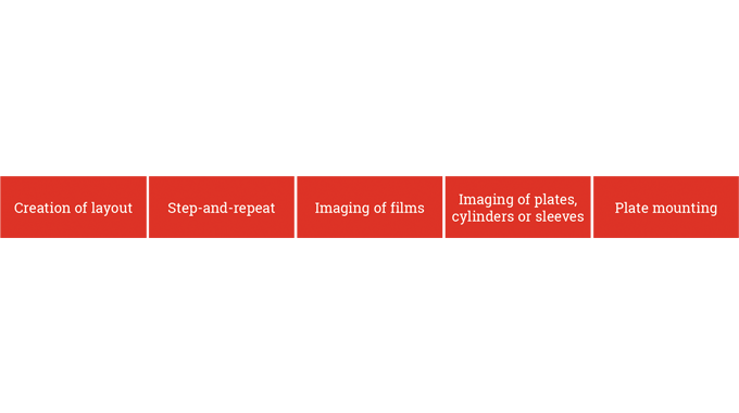
Also included in this activity is the accurate mounting of the printing plate and the assembly and checking of the tools and ancillary equipment used for the embellishing and converting processes. All these items are very important factors in the production of high quality print and embellishments and are highlighted in the flow chart below.
PRE-PRESS ELEMENTS
The following list identifies the areas which are Plate mounting important to achieving a fast efficient job change over and press make-ready.
-
Accurate agreed technical and manufacturing specification
-
Accurate layouts for the step and repeat process
-
Imaged film (depending on the process to be used) See Figure 5.2
-
Conventional plate imaging system (depending on process to be used)
-
Computer to plate (CtP) imaging for the litho, flexography, silk screen and gravure printing processes (dependent on the process to be used)
-
Accurately matched inks and ink draw-downs
-
Print cylinder specifications
-
Tooling data for embellishing, converting and finishing operations
REASONS FOR LACK OF CONSISTENCY
Within the pre-press arena the following list highlights the main areas that can create production difficulties and therefore additional costs.
-
Deviation from the manufacturing specification
-
Use of unapproved suppliers
-
Image integrity and control
-
Incorrect die-cutting profile
-
Change of specified print processes
-
Inaccurate press specification
-
Print/embellishment variables
-
Substrates characteristics
PRE-PRESS AND DOT GAIN CONSIDERATIONS
Before imaging the printing plate, the digital files need to be modified to suit the feedback from the press fingerprinting exercise and therefore make allowances for any variations.
Printing processes tend to have a natural condition where the operation is at its most stable for a given set of solid ink densities. This natural condition may not have the desired dot gain or ink trapping requirements to give a good representation of the desired result. This condition must be compensated for (see the article on dot gain and fingerprinting).
PRE-PRESS LAYOUTS (IMPOSITION)
When the print layout is being planned, due consideration should be given to ensuring that the layout gives optimum production yield and that the amount of substrate that is required for the job is minimised, in order to reduce waste.
Often referred to as imposition, print layout is one of the fundamental steps in the pre-press preparation of a print job. Correct imposition minimises printing time by maximising the number of impressions on a web, thereby reducing cost of press time and materials.
In addition the layout should enable the printing, embellishing and converting operations to be carried out within the parameters of the press and the ancillary equipment being used. For instance consideration should be given to the various inking requirements between one part of a plate and another.
If a design calls for heavy solids together with areas of fine detail it may prove expedient to split the color between two printing stations: one to handle the heavy inking and the other to deal with the fine detail. Alternatively this issue can be overcome by introducing an additional screen tone to print underneath the solid area.
Once the optimum layout has been established the step and repeat data can be generated.
The step and repeat file is then used at the film process and plate imaging stage.
STEP-AND-REPEAT
Step-and-repeat is the action of reproducing a number of design images onto film and subsequently the plate, permitting the label design to be printed as more than one label at a time (Figure 5.3). This speeds up production by reducing press running time. In digital workflows the steps-and-repeat designs are imaged directly to plate.
The step and repeat program determines the number of images to be accurately stepped around the printing cylinder circumference and the number of images across the web width.
This is referred to as the number ‘across’ and the number ‘round’. An example would be 7 labels around and 5 labels across yielding 35 labels per revolution of the print cylinder.
The step and repeat data is used for conventional film imaging and computer-to-plate (CtP) imaging.
ON PRESS CONSIDERATIONS
Modifications to files may need to be made in order to anticipate substrate movement (shrink or stretch) that can occur due to heat, moisture content/humidity (see Figure 5.4)
IMAGING THE PRINTING PLATE
There are two methods used for imaging the printing plate;
-
Film based imaging where an imaged film is contacted with the plate and exposed
-
The more commonly used CtP (Computer to Plate), where the digital file is imaged directly onto the plate.
COMPUTER TO PLATE (CTP)
With CtP plate imaging a number of the process operations, that are required when using film imaging are removed.
Printing plates are imaged using digital data direct from a raster image processor (RIP) and the image is created using a laser to write the image onto the printing plate, screen mesh or print cylinder. In this way the image distortion caused by the use of film is eliminated and aspects such as dot gain can be controlled more effectively.
The plate making process for each of the major printing systems used in the manufacture of self-adhesive labels is explained below.
LETTERPRESS
Letterpress plates have a photopolymer layer on a metal or polyester base. The plate making procedure is quick and easy and a plate can be ready for the press within 1 to 1.5 hours depending on plate thickness (see Figure 5.5).
The procedure for most types of plate is as follows:
Exposure to UV light through a matt negative film with a maximum density of 3.5 log density causes the image relief area to polymerise or harden. The log scale refers to the amount of light that can be transmitted through a solid area of exposed film.
The lower the amount of light the better the finished plate will be. Wide exposure latitude is provided in order that reversed out images can be exposed, along with normal type and image matter.
Exposure times may vary from one batch of material to the next, therefore it is always advisable to make a test plate when a new batch of plate material is opened. A standard negative should always be kept for this purpose, so that better control can be exercised over the results obtained.
Exposure units may be flat or rotary. If a plate that is to be run on a rotary press is exposed in the flat, due allowance should be made for the distortion that will be created by the curvature around the printing cylinder (known as dispro). The exposure operation is designed to polymerise or harden the areas of the plate that are required to print the image, which is the reason for using negatives for exposure purposes.
The image appears as clear film allowing direct access of light to the surface of the unexposed plate.
Wash out
The majority of plate materials are now formulated to permit washing out using plain tap water with few additives. However, for materials requiring special wash-out liquids, the manufacturer's instructions should be carefully followed.
The washing action may be achieved with direct sprays, pads, or brushes. Care must be exercised to ensure that the used wash-out fluid is disposed of correctly and the maker's recommendations followed regarding rejuvenating, recycling, or disposal.
After treatment
This process ensures that no trace of water or wash-out solution remains on the plate. Wiping with a sponge followed by blowing with compressed air is a recommended procedure, ensuring that the still soft surface is not damaged.
Plate drying
In order to rid the plate of any liquid absorbed during the wash-out sequence, it must be thoroughly dried. The working life of the plate will, to a large extent, be determined by the effectiveness of this drying sequence.
Drying times may vary according to the type and thickness of plate material and could (subject to the maker's recommendation), be between 30/80 minutes. It is important that adequate amounts of fresh air are circulated over the plate throughout the drying procedure.
Saturated air will adversely affect the quality of drying and extra time will not necessarily compensate for this. Once fully dry the plate is ready for mounting and use on the label press.
FLEXO
Plates versus sleeves
As with letterpress most flexo plates are based on photopolymer material which is sensitive to UV light. There are however, some flexo plates that are made of elastomer, where the image is engraved by laser and not exposed. Both materials are available in flat or cylindrical form (called ‘sleeves’). Sleeves have been successfully used in mid and wide web presses for packaging printing for many years. These systems are now also available for the narrow web presses for label printing.
Plate build up and thickness
The traditional flexo plate has a polyester (PET) carrier film which is very important for the dimensional stability of the plate. The main photopolymer layer is laminated with the PET film. There is a protective film on top of the photopolymer layer called a cover sheet.
The film is removed before exposing the plate. This film protects the photopolymer surface from scratches or other damage during transportation or handling.
Within the next few years this plate will disappear from the market. The new generation of flexo plates are direct imaging plates. The structure is the same as a traditional flexo plate, but it has a black ablative layer, also referred to as a LAMS layer (Laser Ablation Mask) on top of the photopolymer layer. (See section on flexo plate imaging below).
Different plate thicknesses are available on the market depending on applications. The plate thicknesses mainly used for label printing are 1.7mm and 1.14mm.
Flexo plate imaging
Two methods of imaging the flexo plate are available:
-
CtP (Computer to Plate) imaging with a laser.
A negative film is required to image the plate without a black ablative layer. On the surface of the black ablative plate the image is created by ablating or erasing the black layer.
Direct imaging eliminates the need for the negative film and also increases the plate quality e.g. fine negative letters and half tone dots of less than 1% can be imaged on the plate, without any problem.
The general plate-making procedure is similar to letterpress (see Figure 5.5) and involves the following:
BACK EXPOSURE (PRE-EXPOSURE)
The back exposure is carried out from the reverse of the plate with no film in place. This exposure creates a platform base by polymerising the monomer* for better anchoring of printing elements. The thickness of the base has an impact on relief height. The lower the relief height the better the anchoring of fine detail and highlight dots.
* Monomer – molecule forming the basic unit for polymer.
It is advisable to set a standard for the relief height and it is therefore essential to measure the base thickness of the plate by regularly testing the back exposure.
Main exposure
Whether it is a conventional flexo plate or a direct imaging plate the main exposure is needed for both. This is the exposure to the face of the plate material, through the negative, which forms the image detail that will appear on the finished plate. The details (lines, letters, halftone dots etc.) are reproduced according to the transparent parts of the negative, and cannot be influenced later on. The quality of the relief image subsequently produced depends on the quality of the film negative, the correct exposure time, the condition of the processing equipment and other factors.
The exposure time depends on the type and technical condition of the exposure unit, on the type and age of the tubes providing the exposure light, and on the transparency of the vacuum foil which holds the negative in position during exposure.
It is essential that regular test exposures are carried out using a test negative. These tests are required to check changes in the working of the equipment, in addition to any possible variation from one batch of plate material to another.
Wash out with solvent and drying
Those parts of the plate which have not polymerised are dissolved and removed using a water-based solution or solvent during the wash-out process. The depth of wash-out will vary with the type of plate material being used and the amount of back exposure. The manufacturer's guidelines should be carefully followed.
The wash-out time should be restricted to the minimum in order to avoid undue swelling of the material. Swelling will intensify according to the time that the plate is in contact with the solvent. If the minimum wash-out time is greatly exceeded, fine relief elements of the plate may become detached or distorted.
Solvent wash-out solution has almost disappeared from the market. Water-based solution does not swell the flexo plates in the same way solvent does and therefore the plate drying time is reduced.
The wash-out solvent, which has penetrated into the relief layer of the plate material, is evaporated during the drying process.
Maintaining specific drying times and a uniform temperature across the whole plate in the drying unit is essential. Deviations in thickness may occur if the resting and air drying period before printing is too short.
Wash-out - dry
Another type of flexo plate is available, where the wash-out process is carried out without any solution/liquid at all - this is called thermal processing.
After final exposure the plate is mounted in a dry processing device. The plate is heated and the monomer from the unexposed area brushed-out. This is a very clean and environmentally sound process, which reduces the make ready time for the plate, because no drying is required.
Post-exposure
At this stage the whole plate is exposed without the film in position. Depending on the image (solids, fine lines, dots) the main exposure will allow more or less light to affect the plate. As a result there will be parts of the relief that are less polymerised than others. Post exposure ensures that the finished plate will possess uniform properties over the whole surface.
AFTER TREATMENT
Having passed through these various processes the plate will appear tacky to the touch. If a satisfactory printing image is to be achieved this tackiness must be removed.
The after treatment is designed to remove this tackiness from the relief image by using UV light treatment i.e. exposure under a high energy light source. UV light treatment requires individual exposure times for different plate materials.
High resolution plate-making
Plate imaging and processing for the label industry has undergone numerous changes over the years, from camera, film and plate processing, to the newer technologies using some form of computerised system. Certainly, both computer-to-film and computer-to-plate technologies have had their devotees in recent years for the production of flexo, letterpress and dry-offset printing plates.
High resolution plate-making is a development in the processing of photopolymer plates. A typical laser dot size for high resolution imaging of a flexo CTP plate is around 6 micron (as opposed to 12 micron in the case of standard CTP imaging). Imaging flexo plates at a lineature of 175 to 200 lpi creates extremely fine detail on the plate. With the latest high resolution plate-making systems exposing resolution can now increase to 4000 lpi.
The main high resolution plate-making technologies used in the label industry are;
-
Direct imaging on plate by ablating the black layer
-
Imaging via laser exposed negative film
Computer-to-film systems utilise UV beams passing through a film mask to change the surface characteristics of a plate surface, prior to a mechanical washout process, drying and plate hardening.
Computer-to-plate systems based on laser ablation use a laser beam to write an image on to a pre-coated plate surface and in the process destroying the surface coating of the image areas, again enabling mechanical washout, drying and hardening.
Recently new environmentally friendly, computerised plate-making systems have entered the label market. Typical of these new systems is the DigiFlex inkjet C.T.P system which gives excellent quality and high speed plate processing, allowing fast make-readies.
The DigiFlex system is based on a unique ink technology, which gives a very high quality for flexo, letterpress, dry-offset plates and also rotary screens. Creation of the image area on the plate is achieved using a special reactive ink, which is inkjet-printed to produce a UV opaque mask onto a polyester film substrate. The ink chemically reacts instantly with a second reactant on top of the plate to freeze the ink droplets without any time for ink spread. The outcome is a high resolution dot with zero dot gain on the plate and the capability of achieving a 2% dot on the press.
The reactive layer is then transferred from the polyester substrate to the top of the plate using a lamination process. The primer layer, which has no reaction with the plate surface, is washable during the plate development process and can be used with all standard water-washable plates, solvent washable plates, and with rotary screen plates.
After the image has been created on the plate, the rest of the plate-making process remains unchanged, so an already familiar workflow requires minimal adaption.
In Fig 5.6 the DigiFlex plate dots are flatter than dots produced by computer-to-plate laser ablation, enabling easier set-up on the press and better ink capture. Under magnification, the DigiFlex dots are perceived to be sharper and more solid when compared to laser ablation produced dots, which appear more cloudy and grey. Line edges with the DigiFlex system are clearly superior versus laser ablation systems.
Flexo - sleeve build up
The carrier for the imaging surface is a round cylinder or sleeve made of fibre glass. On top there is either a photopolymer layer or an elastomer layer. The cylindrical flexo sleeve has the major advantage that plate mounting is not needed.
Sleeve imaging and processing
In the case of photopolymer sleeves the imaging and processing is the same as for flexo plates, although rather different equipment is needed for plate making.
Elastomer flexo sleeve engraving
This is a direct engraving method, that means imaging and engraving are done in one step by a high powered laser in an engraving machine.
After engraving, the sleeve surface is rinsed with water to remove the remaining burned elastomer. The sleeve is then ready for printing and no further processing steps are required. With the new generation of laser technology it is possible to engrave 200 lines/inch or more.
Another new development in laser engraving technology is available called 3-D engraving.
With this technology it is possible not only to change the relief angle and its shape, but also to undercut the highlight dots. With this undercut it is possible to print fine lines, text or highlight dots, with negligible dot gain.
OFFSET LITHO
Plate imaging
With litho plate-making it is important to appreciate the structure of the plate itself in order to fully understand the imaging process. Figure 5.7 overleaf shows the make-up of the litho plate.
The litho printing plate has a totally flat surface and this is referred to as planographic.
The modern printing plate is covered with a photo sensitive emulsion. In the illustration below, the aluminum base, the primer layer, and the photo sensitive coating are clearly shown.
Film based imaging
Although most imaging techniques now use CtP, film based imaging is still used. The film negative or positive which is created from the digital file is placed in direct contact with the plate and exposed to a UV light source.
The image from the film is transferred to the printing plates using a photographic process. A measured amount of light is allowed to pass through the film negative thereby exposing the printing plate. On exposure a chemical reaction occurs that activates the ink receptive imaged area. The plate is then is developed and the image is chemically fixed. The plate is then ready for positioning into the press. The film based contact imaging is illustrated in Figure 5.7.
Computer to Plate (CtP)
Offset plates are commonly made without the need for film originals. The digital file to be printed is transferred to a CtP device called a plate setter and the image is created using direct laser imaging (see Figure 5.8). After laser imaging the emulsion that remains in the imaged area is removed, leaving it ink receptive.
The CtP imaged plates do not require any chemical processing.
SCREEN
Screen imaging
The screen imaging process works with a screen mesh of nylon or metal strands stretched over a flat or cylindrical frame. The mesh carries a photo sensitive emulsion or coating, which when exposed and processed, washes out the areas to be printed and hardens the coating left behind to become a barrier in the non-printed areas.
Imaging the flatbed screen
An overall photosensitive polymer emulsion coating is applied to the screen material and then dried before a positive imaged film is placed in contact with the flat screen. The screen is then exposed to a UV light source which hardens the emulsion in the non-image areas thus making it insoluble in water. The emulsion in the image area remains soft and the screen is then pressure washed to remove the emulsion from the image areas, before the screen is then dried.
The stages of flatbed screen imaging are illustrated in Figure 5.9.
-
Polyester screen mesh is stretched tightly over a frame of wood or metal before it is emulsion coated.
-
An image is created photographically on the emulsion and the non-image area is hardened.
-
Emulsion in the unhardened image is then removed by pressure washing.
The Squeeges
The function of the squeegee blade in screen printing is to force the ink film through the parts of the screen mesh that forms the printed image.
Print quality will be affected by the type of blade used and the printer will need to select the most suitable blade type. The edge of the blade which is in contact with the screen can be varied in hardness and profile shape and will vary dependent on the type of job being printed. Any damage to the squeegee will affect the print quality.
Rotary screen
The introduction of steel mesh for screen printing led to an important change within the label industry. It allowed the steel screen material to be formed into a cylindrical shape which meant that screens could be fitted into full rotary presses, which are able to run at much higher speeds than the flatbed screen presses.
Steel mesh screens can be produced with a wide range of screen value options allowing the printer to choose the most suitable mesh for each job. This choice provides more control over the volume of ink being printed and allows for very high coating weights of ink to be printed, way in excess of the other printing processes.
The rotary screen process adopts exactly the same principles as the flatbed system, but with some key differences. The imaged screen is formed into a cylindrical shape whilst the squeegee blade is placed into the screen cylinder in a fixed position. The screen cylinder which then holds the liquid ink rotates at the same speed as the web being printed and the ink is then forced through the imaged area of the rotary screen and onto the substrate (Figure 5.10).
Rotary screen imaging with film
The imaging of a rotary screen cylinder when using a positive film is very similar to the imaging of a flatbed screen. The rotary screens can be supplied to the printer already made up into the cylindrical shape (Stork system) or can be supplied as flat sheets that are then formed into the rotary cylinder by the printer (Gallus ‘Screeny’ system).
With all rotary screen systems an end ring has to be fitted into each end of the screen cylinder. This gives the rotary screen the necessary stability and ensures that the screen rotates evenly during the printing operation.
The procedure for imaging rotary screens used in the label industry is as follows :-
-
Metal screen formed into cylinder and end rings fitted.
-
An overall photosensitive polymer emulsion coating is applied to the screen material and then dried.
-
The positive imaged film is accurately positioned in direct contact with the screen and then secured to allow the screen to spin in the exposure unit.
-
The screen plus the secured film is placed into the exposure unit and exposed to a timed UV light source whilst the screen is rotating.
-
The emulsion in the non-image area is hardened and becomes water resistant.
-
The rotary screen is removed from the exposure unit, the film is removed and the screen placed in the wash out unit, in which the screen is pressure washed to remove the emulsion in the image areas.
-
The screen is removed from the wash-out unit and dried before making ready for the press.
Rotary and flatbed screen CtP imaging
Computer to screen imaging of both flatbed and rotary screens is now widely used. This method of imaging removes the need for film originals and eliminates the exposure process, power washing and drying of the screens.
The digital file which contains the image to be printed is transferred to the imaging unit.
A high powered laser then ‘burns’ the emulsion away, creating the image directly onto the screen. Laser engraving is a digital method of imaging both flatbed and rotary nickel screens. It involves the removal of the emulsion coating in the image areas (i.e. the open areas of the screen). After this the screen requires no further processing and is ready for fitting into the press. In the case of rotary screens, the screen is imaged using a rotary CtP unit, whereas in flatbed imaging the screen remains flat.
CtP imaging reduces the costs associated with the multiple process operation needed when imaging by the traditional method of film contacting. A direct engraved screen produces excellent quality and consistency, with screen resolution of 2540 dpi being produced, to allow fine line work with high contrast to be delivered.
Screens can typically be imaged in 15-20 minutes and because the lengthy drying process is eliminated productivity can be improved, giving a much faster turn round compared to the conventional screen imaging method. Screen material is expensive, but the ability to re-use and re-image screens, especially the rotary screens, has allowed some printers to include a facility which involves stripping off the unwanted image and recoating the screen.
GRAVURE
Gravure cylinder imaging
Gravure cylinders are made of steel and plated with copper. The image area on a gravure cylinder consists of ‘cells’ that are engraved to differing depths and/or sizes to give the variations in dot size and cell depth. The depth of the cell controls the amount of ink and thereby the strength of color being laid down at a particular part of an image. Very subtle variations in both color strength and fine detail can be achieved.
In the past gravure cylinders were chemically etched, but today the engraving is done using a system which uses a rapidly oscillating diamond tipped stylus. Alternatively the gravure cylinders are imaged using digitally driven lasers to engrave the image.
This system removes the problem of inconsistency of the image when a duplicate cylinder is required. With direct digital engraving the image can be simply created and manipulated via computer software.
Worn or obsolete cylinders can be stripped of their image and the base cylinder reused for other printing jobs.
PLATE MOUNTING
For the purposes of this module certain basic principles that need to be followed when mounting plates will be outlined. The complete detail of actual mounting may be obtained from other publications or from the suppliers of equipment designed for the purpose.
The one rule that must be followed in plate mounting is to ensure that the plate will be in the correct position at the first attempt at mounting.
Figure 5.11 illustrates the correct mounting of a plate by hand using the guidelines engraved on the surface of the print cylinder.
Removal, especially of relatively pliable flexo plates, with the purpose of 'trying again', is very likely to stretch the plate at some point, thus making it almost impossible to place the plate so that it is correctly positioned over the whole of its area.
Figure 5.12 illustrates the optimum method of mounting flexible printing plates around an impression cylinder. The aim should be create a continuous surface that will equalise the pressure across the cylinder. Failure to do this will create an unwanted jarring contact bounce.
A well made plate, correctly mounted on a press which is not regularly maintained, will not provide an accurate printed image. The key areas to check, on a regular basis, in order to achieve accurate printed images throughout a run include bearings, anilox rolls, print cylinders, gears, and of course, general cleanliness. Bearings do wear, in fact wear commences the first time the press is started up - that is the reason why they are fitted in the first place.
They are intended as a tightly fitting, but easily replaceable part that can be changed in order to avoid shafts running out of line. In theory they take up stresses and strains caused in parts of the press by heavy tooling, continuous running, heating up etc. The length of life of a bearing will depend on the type of bearing fitted and the amount of stress applied to it. Under a program of planned maintenance all bearings should be cleaned and checked for wear and effective lubrication.
In the flexo, letterpress and litho print processes the print cylinders carry the printing plate and are required to retain even contact with the ink transfer roller and the surface of the substrate being printed or in the case of litho, the offset blanket. There is very little room for deviation from the perfectly true running of the print cylinder. The aim should be for them to revolve within an accuracy of ±0.025 mm.
This will ensure that the pressure applied to both adjacent rolls is reasonably constant. Any measurement, when checking for such tight tolerances, should be made when the press has been running for around thirty minutes. This will ensure that the running parts have warmed up and that any expansion has been taken into consideration.
Double sided tape is used to hold the printing plate to the surface of the printing cylinder (see Figure 5.13).
Some tape manufacturers have a thin layer of foam within their tape which goes some way to smoothing out small deviations in the revolving plate cylinder. With or without such addition these tapes do vary in thickness between one producer and another.
This variation in thickness must be allowed for when determining the final diameter of the print cylinder. If this is not done accurate register will not prove possible. Also, the same brand of tape should be used on each set of print cylinders, unless the object is to compensate for a slight under or over sized cylinder out of a multi-color set.
Cylinder gears
Gears are required to do more than just transfer power from one point of the press to another. When the gear is manufactured it is intended to be meshed at a certain depth with the gear it is driving. This is called the pitch diameter. When meshing the print cylinder gear with the impression roller this pitch diameter is critical to accurate register (see Figure 5.14).
Too deep or too shallow a mesh will cause loss of register between one color and the next. In process color work, the gear for each color should be set to an identical mesh and checked during a run for deviation, caused through increased temperature or mechanical fault.
Regular lubrication is preferred to intermittent applications as this will maintain a constant film of oil and even out temperature fluctuations.
Gearless printing with direct servo drives is state of the art. It eliminates those problems mentioned above and saves time for plate and cylinder mounting.
Print cylinders
When determining the actual print cylinder size on the basis of repeat length in inches, millimeters or number and size of teeth allowance must be made for the thickness of the printing plate and mounting tape and for the effect of pressure and thermal expansion in the cylinder.
To take an example:
A repeat length of 12 inches (or 96 1/8" teeth) equals an effective circumference of 304.8 mm, but the cylinder itself must have a circumference that is smaller by 3.14 times two thicknesses of plate and mounting tape – say 3.14 x 2 (1.7 + 0.3) mm and a small allowance should be made for the mutually opposing effects of compression and thermal expansion, say 0.01 to 0.03 mm.
Ideally there should be no slack between the print cylinder shaft and gear wheel and also none between the internal diameter of the cylinder bearings and shaft. The whole assembly should fit together snugly.
Any movement between these surfaces will upset the intended pitch diameter and show up as loss of register between one plate and another (Figure 5.15).
On-press controls
A key role of the repro process is to ensure that the press is set–up to the optimum specification and that the correct press settings are maintained throughout the length of the print run.
Although the modern repro process can deliver a highly accurate and consistent reproduction of the original image, factors within each individual printing process and limits on engineering tolerances and wear on the press itself, can adversely affect the desired printed result.
A skilled printer has the facility to make on-press adjustments to vary/improve the printed result to achieve the correct tonal value and color.
These adjustments will vary dependant on the printing process being used.
The following paragraphs highlight the areas where on-press settings and adjustments can be made to assist in overcoming any shortfall that may occur in the printed result.
With all the conventional print processes it is possible to make adjustments to the inks being used in order to achieve the correct match. This is called ink mixing and it allows the printer to make fine alterations to the color and also introduce additives to improve the ink performance.
LETTERPRESS
The most effective method of color adjustment on a letterpress machine is the ability to control the volume of ink delivered to the printing plate. The letterpress ink distribution system has an ink reservoir called an ink duct.
The ink duct allows the printer to adjust the volume of ink being delivered to the distribution rollers thereby controlling the strength of the color. A reduced volume of ink will give a lighter color and a heavier volume will increase the color strength.
There is very little ‘give’ in the letterpress printing plate, so in order to achieve a good ink film transfer and a sharp image, the pressure between the printing plates and the impression cylinder or flatbed requires very careful setting.
A skilled operator will vary the hardness of the impression roll ensuring that the plate to substrate contact is a ‘kiss’ touch. Careful balance of pressure between plate and impression roll is crucial as it determines the print quality (Figure 5.16). Too much impression creates a squashed or halo effect and too little impression creates missing dots and poor print.
Accurate inking roller to printing plate settings is very important and adjustments to the printing pressure should be made throughout the press run, to make sure the correct pressure is maintained.
FLEXO
Flexographic anilox rollers in particular are subjected to considerable abrasive wear and careful monitoring of the ink densities and viscosities delivered by the anilox roller is therefore very important (Figure 5.17). It is strongly recommended that each roller is regularly inspected for any damage or reduction in the cell depth.
The depth and shape of the cells is a key factor in the efficient delivery of a uniform ink film to the printing plate and allows the operator to vary the volume of the ink film by changing the anilox roller, to the achieve the correct color The number of cells on an anilox roller are measured in cells per linear inch (CPI) or the cells per centimeter (CPC).
As the cell count increases the ink film delivered to the printing plate decreases, (Figure 5.18). It is very important that the printer uses thin anilox roller which delivers the correct ink film, which matches the repro specification.
It is recommended that a record of the ink volume of each anilox should be kept to ensure that the anilox specification is correct for the each print job.
Poor quality flexo printing is usually a result of a soft printing plate, too much impression and a low viscosity ink. Flexo plates are relatively soft compared to the much harder letterpress plate and this soft construction can affect the print quality.
A softer plate will transfer the ink film smoother than harder plates, but the likelihood of a squashed effect on the printed dot increases. The squashed dot can easily be identified by a halo effect on the printed dot.
The correct pressures of anilox to plate and plate to substrate must be established at the initial stages of the job make-ready. Incorrect settings will adversely affect the shape and size on the dot.
One of the biggest problems confronting the printer is the problem of dot gain. This effect is created by an ‘increase’ in the specified printed dot size which affects both the tonal values and therefore the color being printed.
Dot gain can be a result of incorrect plate imaging, but is generally a result of incorrect impression settings or poor engineering or wear on the press.
The printer must ensure that the correct settings between the anilox roll, the printing plate and the substrate are set correctly and maintained throughout the print run.
LITHO
The most effective method of color adjustment on a litho press is the ability to control the volume of ink delivered to the printing plate. The litho press ink distribution system has an ink reservoir called an ink duct. The ink duct allows the printer to adjust the volume of ink being delivered to the distribution rollers thereby controlling the strength of the color. A reduced volume of ink will give a lighter color and a heavier volume will increase the color strength.
In the litho process the inked image is transferred from the plate cylinder onto the offset blanket, which in turn transfers the printed image onto the substrate. The pressure settings between the plate, blanket cylinder and the impression cylinder are important and need to be set correctly. The settings will be dependant on the type and thickness of the substrate being printed (Figure 5.19).
Offset blankets are made of synthetic rubber. The shore hardness of the blanket can vary allowing the printer to choose the correct blanket hardness for a particular substrate. It is important that the release factor of the blanket is correct so that the inked image is fully transferred to the substrate on every revolution of the printing cycle. Ink residue and fibres from the substrate surface can contaminate the blanket and regular cleaning throughout the print run is recommended.
The printer must establish the optimum damping settings during the make-ready process and throughout the print run. The control of the damping process is critical in achieving the correct print quality. Any imbalance associated with insufficient damping will allow the ink film to contaminate the non-image area and this will result in ink being deposited in the non-image area, thereby creating scumming or catch-up.
The problem of plate scumming can be affected by an increase in the ambient temperature around the press and also the heat generated when running the press at speed.
SCREEN PRINTING
The size and depth of the mesh material and the viscosity of the ink are the key areas that control the quality of the screen printed image.
It is most important to select the correct material and mesh count to suit the graphic requirement and the thickness of the ink film that is required. Mesh selection will impact on the print detail, the stability of the screen and on print registration (Figure 5.20).
The correct viscosity of the ink is also very important in the screen process.
The ink must be viscous enough to avoid passing through the screen cells until the exact moment of the printing cycle when the ink is forced through the screen cell by the pressure of the squeegee blade.
Inks with thixotropic properties (this is an ink that thickens up and affects the flow properties of the ink) can offer some advantages to the screen printer, as it becomes fluid when agitation takes place or pressure is applied i.e. via the squeegee blade.
The printer must ensure that the ink is adjusted to the optimum viscosity and this must be maintained throughout the print run. Changes in ink viscosity will affect the color strength and the use of a Zhann cup* measurement is recommended to verify this viscosity.
*Zhann cup - dip calibrated viscosity measuring device. A stainless steel cup with a tiny hole drilled in the center of the bottom of the cup.
After lifting the cup out of the ink, the user measures the time until it stops flowing to assess its viscosity.
The type of squeegee blade being used can also affect the print quality and the volume of the ink deposit. A soft squeegee will deposit a thicker layer of ink than a harder squeegee and therefore affect the volume of ink being deposited onto the substrate.
The hardness of the squeegee blade is measured in shore hardness and each type is color coded:-
-
Yellow has a shore of 55-60 and is suitable for solid work
-
Red has a shore of 65-70 and is suitable for solid and line work
-
Green has a shore of 70-75 and is suitable for text and line work
-
Blue has a shore of 75-80 and is suitable for fine text
The variation in the volume of ink may be small but this can make the difference when matching the exact color specification.
The profile of the squeegee can also affect the ink volume being printed and also the print quality, dependant on the content of the image being printed. Squeegee blades are available with different profiles on the leading edge of the blade, i.e. square edge, round edge and bevelled edge being the profiles in common use (Figure 5.21).
A round edge will give a heavier ink volume, but when printing fine definition work the bevelled edge would be more suitable.
GRAVURE
With gravure printing the adjustments that can be made on the press are limited.
As the gravure process prints directly onto the substrate from an engraved cell, in which the size and depth of the cell have already been predetermined, this means that the volume of ink transferred to the substrate cannot be changed i.e. there is no adjustable ink duct, inking rollers or anilox roller used in the gravure press (see Figure 5.22 and 5.23).
The two areas that can be adjusted by the gravure printer are the ink viscosity and the angle of attack of the doctor blade. The printer can make adjustments to the ink formulation to achieve the correct color match, but it is most important that the correct ink viscosity is
established and maintained throughout the print run.
Any variation in the ink viscosity will result in color variation during the print run.
Changes to the thickness and angle of the doctor blade (‘wipe’) can impact on the ink volume delivered. For example a thicker blade and a shallow wipe will allow a slightly thicker film of ink in the cell, whilst a thinner blade and a steeper angle of wipe will leave slightly less ink in the cell.
SUMMARY OF ON-PRESS SET-UP AND CONTROL FACTORS (BY PRINT PROCESS)
Letterpress
-
The volume of the Ink film can be controlled by the printer
-
Inking/forme rollers settings must be correct
-
The plate to substrate setting needs to be finely set and maintained
-
The rubber covering on the impression roller can be varied in shore hardness
-
Ink mix formulation can be adjusted by the printer
Flexo
-
The anilox roller can be changed to suit the correct volume of ink required
-
The anilox to printing plate and the plate to substrate/impression roller has to be finely set and this setting must be maintained throughout the print run
-
The ink mix formulation can be adjusted by the printer
-
The correct ink viscosity must be established and maintained
Litho
-
The correct balance between the plate damping and plate inking must be maintained
-
The settings between the plate cylinder and blanket cylinder must be correct for the substrate being printed
-
The offset blanket must have the correct release factor for the substrate being printed
-
The offset blanket has to be washed regularly and be free from debris
-
The volume of the ink film can be controlled by the printer
-
Inking/forme rollers settings must be correct
-
The ink mix formulation can be adjusted by the printer
Screen Printing
-
The correct mesh for the graphics required has to be established before the screen is imaged
-
The ink has to be at the correct viscosity
-
The squeegee blade has to be the correct hardness/softness for the graphics required
-
The type of profile used on the squeegee leading edge will affect the printed result
-
The ink mix formulation can be adjusted by the printer
Gravure
-
The ink mix formulation can be adjusted by the printer
-
The ink viscosity must be correct, as any fluctuation will result in color variation
-
Increasing or decreasing the angle of wipe and varying the thickness of the doctor blade will impact on the volume of ink delivered