Depending on the type of label and the printing and/or die-cutting requirement, the mechanical die-cutting operation may be performed using flexible, solid rotary or flat dies made from steel or, most recently, using digital laser die-cutting technology.
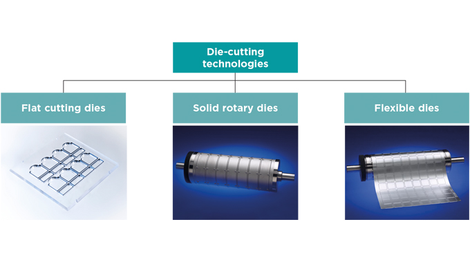
The process of cutting and separation of the processed material using cutting tools is known as die-cutting (shearing) and is probably the most critical in terms of the final end-use application of the label. This shearing or die-cutting is known as a non-chipping process (no material is removed during the separation).
Historically, flat steel die-cutting tools were the dominant technology used on the early intermittent feed and semi-rotary presses of the 1970s and 1980s. As rotary printing started to become the major label printing process so the industry moved to solid rotary dies. More recently, flexible dies have become the die-cutting process of choice, overtaking solid tools for many applications.
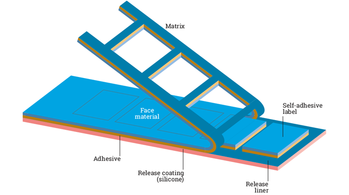
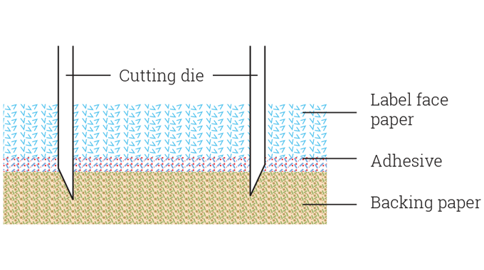
In operation, the cutting die must cut cleanly through the label face material and the adhesive layer, but must not cut into or through the silicone coated backing release liner. Die-cutting is therefore an operation that requires precision and fine control of the cutter manufacturing process. This would include the choice of cutter materials and their properties as well as the cutter set up in the printing and converting machine. In turn, then, a constant thickness is required for the laminate and the release liner backing material. Figure 2.2 illustrates how the matrix waste needs to be peeled away cleanly after the die-cutting process has taken place.
Essentially, the cutting die - whether flat, solid rotary or flexible - has to be tooled to the thickness of the backing liner and, if this varies and the die cuts into the liner, as in Figure 2.3 (known as die strike), then the die will have to be re-set or the material evaluated for required settings. If the die-cutting is too heavy, or too light, and the adhesive has not been cut through cleanly, then labels will not dispense correctly and may not even separate at the beak or stripper plate on the label applicator, instead remaining on the backing liner and staying on the web.
Thickness variations from place to place in the backing liner will also cause problems.
If the adhesive has not been cut through cleanly or has bled, or there are blobs on the surface, then further problems may arise due to the applicator rollers gumming up.
In this article we will be examining the properties of die-cutter tooling materials and explaining the die-cutting process, either performed using flatbed dies, rotary solid dies or with flexible dies.
DIE-CUTTER TOOLING MATERIALS
Die-cutting tools, whether flatbed, semi-rotary or rotary, are prepared using tooling steels that require specific properties, particularly the following:
The first three of these properties are inherent to tool steel. Hardness is another property in tool steel that is developed through a heat treating process. So let’s examine these requirements before looking at the different types of cutting dies and their manufacture and performance.
Toughness is the ability of steels to resist cracking, chipping or breakage. Toughness is usually measured in foot-pounds of energy required to break the steel. Steel in its simplest form is very tough. As alloying content is added, steel loses some of its toughness. Low alloy grades of steel will have better toughness than higher alloy grades.
Wear resistance. A tool is in constant movement, either against another tool or work material. This constant movement can wear away the surface of the cutting tool. The tool will therefore need to have some amount of wear resistance. Wear resistance is the steel’s ability to resist erosion. Wear resistance in tool steel is achieved by the presences of carbides. Chromium, molybdenum, tungsten and vanadium are the four carbide-forming elements commonly found in tool steels.
The various carbides are listed in the order of the hardness of the carbides that they form. So a tool steel with vanadium carbides should have more wear resistance than a tool steel with the same amount of chromium carbides. Many tool steel grades will have more than one type of carbide to balance with the other properties. Wear resistance testing is non-standardized, but the grades are always compared in relation to each other.
Heat resistance is the third inherent property of tool steel. It is the steel’s ability to resist softening when exposed to heat while in operation. This is a very important property in high-speed steel tools. Excessive heat in a turning or milling operation can lead to the softening of the tool. This softening could allow a tool to dull or chip causing premature failure. With the addition of tungsten and/or cobalt in high-speed steel, heat resistance is improved.
Hardness is a very important property of tool steel that is developed during the heat treating process. It is not one of the inherent properties of tool steel. Hardness is developed through the addition of carbon. A minimum of 4 per cent carbon is needed in order to achieve the hardness necessary for tool steel. Hardness is the steel’s ability to resist compression, indentation or deformation. Without hardness the tool would collapse. Hardness is directly related to compressive strength. Hardness is typically measured on a Rockwell C-scale. Tool steel at Rc 62 will have higher compressive strength than tool steel at Rc 55, regardless of the grade of steel chosen.
Subsequent hardening of tooling steels can be carried out using case hardening, induction hardening, vacuum hardening or laser hardening, briefly explained as follows:
-
Case hardening or surface hardening is the process of hardening the surface of a metal object while allowing the metal underneath to remain soft, thus forming a thin layer of harder metal (called ‘the case’) at the surface. Case hardening is usually done after the part has been formed into its final shape.
-
Induction hardening. This is a form of heat treatment in which a metal part is heated by induction heating and then quenched. The quenched metal undergoes a transformation, increasing the hardness and brittleness of the part. Induction hardening is used to selectively harden areas of a part or assembly without affecting the properties of the part as a whole.
-
Vacuum hardening. Vacuum hardening of solid tooling is mostly done in a so-called vacuum furnace which is a type of furnace that can heat materials, typically metals, to very high temperatures and can carry out processes such as heat treatment with high consistency and low contamination.
-
Laser hardening. As an alternative to the more common surface treatments, some suppliers of flexible dies also offer laser hardened dies. Laser hardening is not offering any reduction in the friction coefficient, but does offer a partial increase in hardness at the tip of the cutting edge. The increase in hardness depends on the carbon content in the steel and not on the energy put in by the laser.
Tool steel selection. Selection of a tooling steel is a balance between the four properties already described above. No single tool steel will provide the best of all of these properties. Other factors also play a role in tool steel selection. Every one of the tool steel’s used must be machine-able in order to form it into a useful tool. Machinability is usually expressed as a percentage of the most basic tool steel, which would be valued at 100 per cent machine-able.
Many tools will also require some degree of grind-ability. Tools are usually manufactured to very close tolerances and grinding is performed to achieve these close tolerances.
Tools may also require some degree of polish-ability to allow the manufactured part to release from the tool. Fine-grained or powdered metal tool steels allow the highest degree of polish-ability.
Some other important properties of tool steels include distortion and safety in heat treating, austenizing temperature range, price and availability.
FLAT DIE-CUTTING PROCESS AND TOOLS
In the earlier days of pressure-sensitive label production, all cutting units were flatbed. A flatbed cutting unit is characterized by the fact that the converted material is not moving relatively to the cutting tool. The cutting tool is punching in to the material while the material is stationary during the cutting operation. After the cutting sequence has been completed, the material is moved forward to the next position, where the cutting sequence will be repeated and so on. Flatbed cutting dies are used on all label printing machines with flatbed units, including semi-rotary label presses (Figure 2.4).
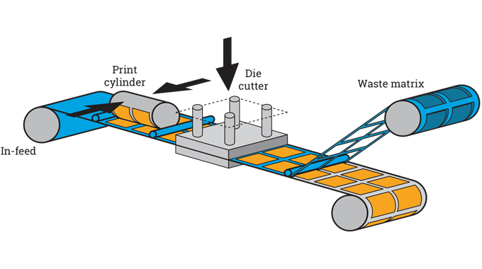
In one sequence, the entire cutting rules of the cutting tool are being punched in to the material at the same time. This will require a relatively high cutting force because of the amount of cutting taking place in one operation at the same time. In a flatbed converting unit, the cutting depth has to be adjusted to the actual thickness of the face material and adhesive.
As can be seen in the diagram, the configuration of a flatbed die-cutting operation consists of three main elements:
-
The in-feed: Which takes control of the web and registers it to the cutting tools
-
The flatbed platen section: This is the heart of the unit, bringing the cutting die and cutting plate together under pressure. Held between them, the substrate may be flatbed die-cut, creased, or even perforated depending on the particular application and substrate
-
The stripping section: Matrix waste, and sometimes side and rear trim, is removed using a matrix re-wind spool or roller
If we look at pros and cons for this type of flatbed die cutting unit we can see the following key advantages and disadvantages:
Advantages
-
The cutting tools used for this type of cutting are relatively simple and therefore also relatively inexpensive.
-
Because a flatbed cutting unit has the ability to adjust the cutting depth, the same cutting tool can be used for different material thicknesses and can both kiss cut and cut through the material.
-
Is good for short run work.
-
Offers easy access for the operator.
Disadvantages
-
Compared to rotary cutting, flatbed converting is a slower process and the initial adjustment of the cutting tool is more time consuming than in a rotary converting process.
-
They are not as robust as solid dies.
-
Mainly for productivity reasons, flatbed die-cutting technology is less widespread today in the pressure sensitive industry.
Cutting tools for flatbed die-cutting units typically consist of steel rules which are held in place in grooves cut to shape in a wooden or plastic base material. Nowadays, flexible dies are also used for flatbed die-cutting in conjunction with a precision-made magnetic base plate that holds the flexible die in position.
Because of the force required for flatbed die-cutting . with the entire cutting operation undertaken simultaneously . the flatbed die-cutting unit is usually a heavy and solid piece of equipment with very good stability for the cutting process.
Steel rules used for flatbed die-cutting of labels are usually positioned to the desired label shape(s) by using a jigsaw, vertical milling machine or a laser beam to cut grooves in a plywood or plastic base. Cutting rule is then cut and bent to fit the cut out label shape and inserted into the base.
Wherever practical, for facilitating removal of the waste, rule joints should be positioned so that they run with the web direction and not across the web.
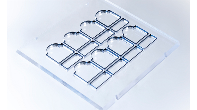
Ejection rubber is fitted to ensure the die-cut web separates quickly and cleanly from the cutter. The amount of rubber required will vary according to the complexity of the label shape. Rubber strips are placed on either side of the steel rule to act as the stripper plate; the rubber compresses on the down-stroke and on the up-stroke it pushes the workpiece out of the die. The rubber used varies in thickness, structure and hardness (Shore or Durometer). It is important to use ejection rubber that is slightly higher than the actual height of the cutting line. This will cause compression (sufficient energy and ejection force) on the rubber thus ensuring complete ejection of the cut out part. Base plate height is commonly between 5 – 10 mm.
Trouble free die cutting of labels requires cutting rules with specific properties. The main requirements are extreme dimensional accuracy, edge straightness and minimal tolerances, sharp cutting edges and bevels (cutting angles) suitable for cutting all types of pressure-sensitive materials, long life, seamless rule joints and easy processing on auto-easy benders. The cutting angles of the rules are adapted to the particular pressure-sensitive or other material to be cut and can vary from 50° up to 110°.
In reference to the cutting rule die blades, the bevel(s) of the cutting edge determine how a blade penetrates and cuts the specific material being die cut . paper, plastic, foil, card, soft, hard, etc. A center bevel for example, may be used for general purpose or cardboard cutting, a side bevel for cutting more rigid materials, a centre face double bevel for the converting of thick or harder materials. See Figure 2.6.
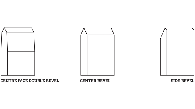
Quite simply, the bevel on a die blade depends on its intended use. The bevel is generally pre-shaped in the blade and can have a short or long bevel, a center bevel, a side bevel or multiple bevels depending on what the blade is to be used for.

The bevel on a die blade is identified by the number of degrees on the bevel or as an inside bevel or outside bevel. Some steel rule blades have a double bevel for specific cutting applications.
Cutting rules are also available in various grades of performance and hardness (described earlier) . including through hardening to give a uniform high hardness on the cutting edge and in the body, induction hardening of the cutting edge and special coatings, all of which can extend the life span of steel rules up to five times, in turn making them particularly economic for multiple repeat jobs and very long life. Label cutting also requires excellent bendability, reduced cutting force and long tool life.
ROTARY DIE-CUTTING TOOLS
Rotary die-cutting uses a solid curved cylindrical or wraparound die in a rotary die-cutting unit, with the cutting taking place against an anvil roller.
See Figure 2.8. While the global focus of label die-cutting today has largely moved, or is moving, to rotary die-cutting using flexible dies, solid steel rotary cutting tools still have a significant presence in the industry, and probably will still have a role to play for many years to come. Some substrates such as thicker papers or films are just not suited to cutting with flexible dies; they are too thick. Indeed, the type of material being cut makes a huge difference when it comes to die selection.
Materials other than pressure-sensitive are also now being printed and die-cut on label presses by an increasing number of label converters. In particular, forecasts of strong demand for more convenient packaging solutions for processed food, fast-moving consumer goods (FMCG), sandwich packs and pharmaceutical and medical products are driving moves to new rotary converting solutions, including innovation in die cutting technology. Both solid rotary die stations and in-line processing with flexible dies are therefore in common usage and combine to deliver dramatic improvements in converting speed, material throughput and process efficiency in an ever-wider range of applications.
Solid rotary tools are manufactured in various grades of hardened steel (described earlier) . determined by the application and the process used to engrave the die. They can be ground/milled on computer numerically-controlled (CNC) machines or by using electronic discharge machines (EDM). Both have an accuracy in range of 0.0025 mm / .0001”.
CNC milled rotary dies. The process of producing solid rotary dies using CNC machines to create the cutting lines starts with the sawing of a tooling steel bar and blank for the gear, followed by turning the shaft, bearer and body of the cylinder. Next up then is the milling of the cutting lines and cutting the gear. The cylinder may be surface hardened prior to machine or hand finishing or after to make it more durable. With the newest technology, many applications allow for tools to be machine sharpened. Doing so allows for even more consistency in finished surfaces.
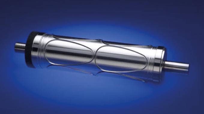
Surface treatments can be added to enhance resistance to abrasive materials, inks and coatings. Non-stick coatings offer a very effective means of controlling adhesive transfer and allowing for the cut of exposed adhesive products.
This finished cylinder will be measured and tested against specifications for quality and performance.
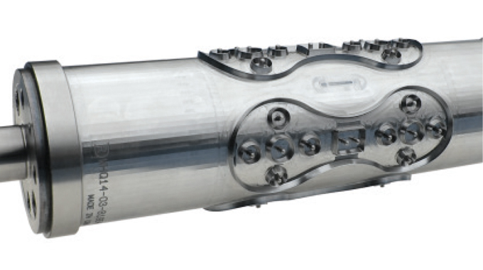
EDM dies. These are rotary cutting dies produced using electronic discharge machining (EDM) by eroding the non-required steel and leaving the cutting lines. The hardening process takes place before the EDM process, thereby reducing possible distortion of the cutting lines/image.
As with solid rotary dies, the manufacturing process starts with sawing the tooling steel and blank for the gear, turning the cylinder and gear and cutting the gear.
Vacuum hardening then takes place before milling the carbon electrode and spark eroding the cutting lines in the EDM machine. Cylinder finishing and testing for quality and performance again take place.
EDM dies provided additional durability for metal-to-metal applications and were also effective for long-run pressure-sensitive jobs, as well as for cutting intricate shapes and designs. Newer technology, though, has the gap closing on these differences between CNC and EDM and the chrome plating of a CNC die can outperform an EDM pressure-sensitive applications.
For the growing numbers of converters using special types of CNC or EDM rotary tooling dies that offer waste removal without contamination of the web there are a number of rotary tooling materials management solutions now available from various tolling suppliers, including:
-
Pin Eject dies remove or eject the cut part from the die cavity with pins.
-
Air-eject and focused Air dies utilize air to eject the waste from the cavity during the converting process.
-
Vacuum dies use vacuum to remove the waste through the cavity and out from a center drill in the die.
Flexible dies are thin, flexible steel die-cutting ‘plates’ for use on magnetic cylinder bases. They are produced from specially formulated steel ranging from 0.5 – 1.5 mm in thickness and are then mounted onto a magnetic cylinder. Flexible dies are lower in cost than solid dies and the economics of use become more attractive as the complexity of the label shape increases. Their life is much the same as for a solid die, providing cleanliness, setting, anvil condition, adhesive and label design are properly controlled.
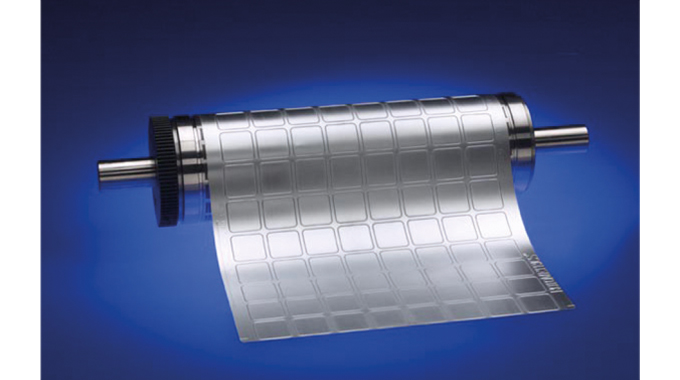
Production of flexible dies involves the plotting of an image directly on the die material so that background material can be removed through chemical etching. CNC mills create the required cutting or creasing lines. Optional processes or features for flexible dies include back grinding, chemical de-burring, laser hardening and coating (non-stick, durability, etc). Before despatch, flexible dies will be tested by the manufacturer on the specified substrate material in a cutting unit.
Flexible dies can be ordered to provide solutions for all kinds or converting requirements, including dies for short, medium and long runs, a wide range of filmic face materials, thin film liners, abrasive substrates and thermal transfer materials, as well as for folding cartons.
Magnetic cylinders used with flexible cutting dies are made from alloy or stainless steel and have a series of permanent magnets glued around their periphery which are used to hold the flexible dies in place. The magnetic cylinders (see Figure 2.12) will fit on to any press that takes rotary dies, and there are no size limitations outside of those relating to the press dimensions. They are installed in exactly the same way that conventional rotary dies are installed. This can be done by the regular press operators or maintenance staff.
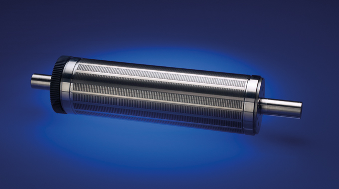
When using magnetic cylinders, press operators will need to become aware of the high standards of cleanliness required, together with an appreciation of the careful handling required to avoid bending or damaging the plate. The skills required for mounting a flexible die are similar to those required for mounting printing plates.
More information on magnetic cylinders is provided in Chapter 7.
DIE-CUTTING UNITS
Whatever the type of rotary cutting . using solid or flexible wrap-around dies . the die-cutting process is basically the same. A web of material will be fed through the press into a die cutting station which holds a rotary tool that will cut out shapes, make perforations or creases and can even cut the web into smaller parts.
A series of gears will force the die to rotate at the same speed as the rest of the press, ensuring that any cuts the die makes line up with the printing on the material. The printing machines can even incorporate multiple die cutting stations, making it possible to die-cut the web in different steps.
The cutting cylinder, either a solid rotary die or a flexible die mounted on a magnetic cylinder, is held in the die-cutting station or unit in a stable position, at the required cutting pressure, so as to perform the cutting operation. Cutting through the face material and adhesive takes place using the cutting die, cutting against an anvil and backing roller supporting the release liner and cutting process.
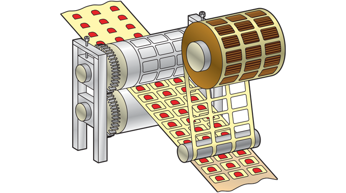
The cutting and anvil cylinders are typically stacked on top of each other in a conventional cutting unit. See Figure 2.13. There are some die-cutting stations, though, that load the die horizontally against the anvil. The repeat size of the cutting cylinder will vary from job to job. A cutting unit is generally constructed so that the cutting cylinders are relatively easy to replace.
The resulting matrix waste after die-cutting is removed using either an in-line matrix removal unit on the press (again see Figure 2.13 or extracted through a vacuum waste unit.
Since there is no stop and go-motion in a full rotary cutting process, the production speed can be greatly improved compared to previously mentioned flatbed die-cutting operation. In its simplest configuration there are no adjustment options for the cutting depth like in a flatbed die-cutting operation.
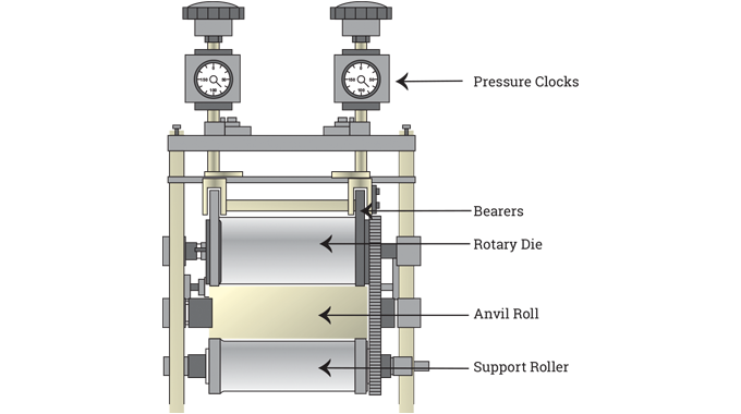
The facility to make very fine adjustment is an important requirement of modern rotary die-cutting units and they are therefore fitted with pressure measurement gauges (see Figure 2.14) which enable the operator to monitor the pressure being applied to the die and avoid any overheating of the bearers and subsequent damage to the die. It is also important that all bearers are adequately lubricated throughout the print run.
Some label shapes can prove difficult during the matrix removal process and careful consideration needs to be given to the job layout to ensure that the removal of the matrix is trouble free and enables a consistent running speed. A number of presses are equipped with a clutched, driven roller (‘capstan’) placed just above the matrix take-off point. The pull speed of the roller can then be adjusted to increase or decrease the tension applied to the matrix and allowing the operator to have more control of the matrix removal process.
Modern magnetic flexible dies can be used to cut almost any conceivable narrow web printing product perfectly – from simple rectangles to multi-layer booklets.
As a guide, the advantages and disadvantages of rotary cutting technology can be summarized as follows:
Advantages
-
Running speeds are greater than that achieved with flatbed die-cutting
-
There is no need to adjust the cutting depth
-
It is easy to monitor the pressure being applied and avoid bearer overheating or die damage
-
Cutting cylinders are relatively easy to replace
Disadvantages
-
The repeat size of the cutting cylinder will vary from job to job
-
Solid rotary dies will be more expensive than flat bed dies
SEMI ROTARY/INTERMITTENT DIE-CUTTING
In the semi rotary (intermittent) die-cutting process, the web travels through the machine with a forward and backward movement and the cutting cycle only takes place as the web travels forward. The cutting unit has a ‘fixed’ magnetic cylinder determined by the press manufacturer’s design,(19” or 25.5” are very common).
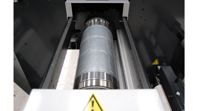
The actual cutting length is defined by the amount of web travelling through the press and this ‘pull’ distance is controlled by the translator feed system, which operates via servo driven cylinders and nip rollers positioned at the infeed and outfeed sections of the machine.
Although the distortion of the flexible dies is based on the circumference of the ‘fixed’ magnetic cylinder, the total cutting image on the flexible die can be smaller. For the tooling supplier, it is important to know exactly the machine type. This information is necessary for choosing the right template (indicating registration marks/positioning holes/etc.) for the flexible die to be produced.
The speed of this die-cutting process is significantly slower than full rotary die-cutting and is mainly used for short runs and the finishing of digital labels.
MALE/FEMALE FLEXIBLE DIES
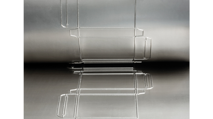
These are a relatively new development using Rotary Pressure (RP) technology. This technology is quite different from traditional crush cutting in which a sharp cutting edge cuts through the material against a solid anvil. In RP cutting (See Figure 2.16), the dies have flat cutting edges and burst the material as they squeeze from both the top and bottom.

Instead of using segmented rotary dies, male-female flexible dies (see Figure 2.17) have been introduced for producing folding cartons, drinking cup walls, etc.
The development of RP male/female flexible die technology responds to customer demand for more flexibility in production, reduced set up times and considerable cost savings in tooling within the packaging industry.
LASER DIE-CUTTING – LIGHT AMPLIFICATION BY STIMULATED EMISSION OF RADIATION
Being able to change the shape of labels on demand and not having to purchase expensive tooling for each shape or size of label . and often delaying the converting line . has meant that laser die-cutting has long excited the label converter. With today’s technology now far superior to that of just 15 or so years ago, it has become faster and more efficient, has a higher cut quality and, if used for the right kinds of applications and markets can certainly both reduce a converter’s costs and create value-added opportunities for many very short run applications.
Laser die-cutters today are able to take any vector-based digital image – perhaps generated on an Esko system and import this into the cutter’s operating software so as to generate the job set-up within a few minutes. Hence the term digital die-cutting. Quite simply, the laser cutter uses programs developed from the step-and-repeat function of label origination to guide the cutting head around each separate label profile. Digital label printers with digital laser cutting can therefore move from the artwork stage to a finished printed and die-cut label within a very short period of time.
In operation, the laser cuts through the face material , either paper or filmic , and stops after the adhesive layer. Laser cutting like this is not cutting in a traditional sense. The laser is either melting, burning or evaporating a thin line through the material.
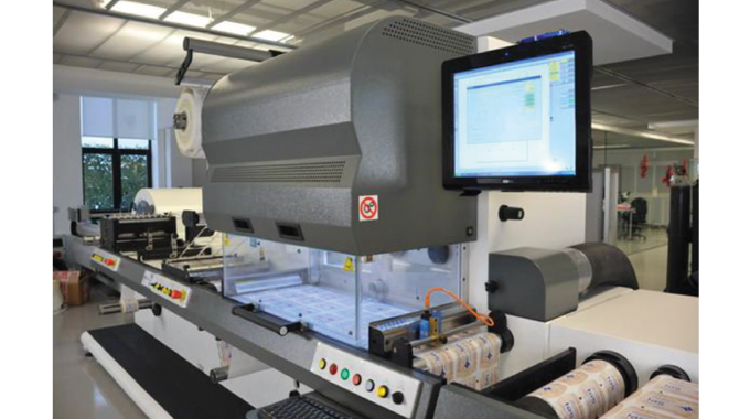
The laser beam is created by the introduction of gas and electric current to a sealed chamber. As the electricity breaks down the gas, energy is released and resonates between mirrors within the chamber. As it resonates it increases in intensity and at its optimum is released through a partially transmissive mirror. The beam is then directed to a focusing lens and is further intensified. At this point the laser beam becomes a usable cutting device.
The laser light is especially hazardous to the human eye and needs a protective shield to prevent any direct or reflected beam that can hit a person. Because the laser is removing material in the form of fumes, it will require extraction. Laser cutting can cut almost all traditional materials depending on how well the material absorbs the laser energy.
Job changeover from one image to another has also been addressed and is faster with the latest laser cutting technology since the next job can be downloaded while the current job is still running. Larger die cut patterns can be loaded plus static pattern cutting for testing small lots of material samples. The images can be easily stepped across the web, the material cut type and cut path selected, with the cutter then ready to go.
Some laser cutting systems today have manual and prompt pattern changes with the ability to store millions of patterns and can also be networked to an art department or the Internet with newly created cutting patterns being immediately available to the operator.
Depending on the supplier, software may be incorporated in the equipment so that the operator can import or create the die line pattern, edit the die line pattern, and then test the die line on a virtual machine before going to actual production of the finished product.
The most important consideration in laser die-cutting is not the linear cutting speed. It is the actual speed that the web moves through the machine, which is governed by the complexity of the artwork and the ability of the software to optimize cutting. Undoubtedly, the best laser cutters are able to automatically optimize the cutting sequence through the software to produce the maximum web speed. Advantages and disadvantages of laser cutting can be summarized as follows:
Advantages
-
The technology offers 100 percent savings in cutter tooling. No dies are required, whether flat, rotary or flexible.
-
Tool-less non-contact laser production offers multiple depth cutting possibilities and can include kiss-cutting, thru-cutting and perforation in one pass.
-
Converters using laser cutters estimate that the savings in set-up waste can be as high as 60 percent.
-
Pattern changes are simple, requiring only edits to drawing files without any downtime for set-up or die creation.
-
Lasers today can be used to cut all shapes and sizes.
-
With few exceptions, lasers can cut most types of substrates.
-
Laser cutting can also be combined with other laser processes such as perforating, scoring, kiss-cutting, etching and ablating.
-
Laser cutting can be used to convert difficult materials, such as abrasives and adhesives, with ease.
Disadvantages
-
Cutting speeds will depend on a number of variables, including material thickness, the amount of cutting required, the amount of small radius curves, the complexity of the cutting shapes, the number of labels across the web, and the amount of jumping between features.
-
The more complex the shape to be cut, the slower the cutting speed.
-
Higher energy costs than conventional die-cutting.
Put together, laser cutting can play a valuable part in a modern label converting plant, working with conventional and digital printing outputs to offer materials and cost efficiencies, reduce waste, provide added-value opportunities, sequential coding and numbering, and more complex shapes and lengths. The technology has a valuable role to play in the future and more label converters will be evaluating the benefits and opportunities when drawing up their investment plans.


